I. Concept
The initial idea for the camera was to create a digital camera with an analogue camera "flaws". I have always enjoyed the hard limit of photos that you can take with an analogue camera and the fact that the photos are not available instantly. However, the film development process has been more and more annoying over the years as it's not as it used to be. Therefore I came up with an idea of a digital camera (no need to develop the film in a lab) that has a 36 photos limit (you need to digitally develop them before taking more) and you can't see the photos until you digitally develop.
II. Overview of the design
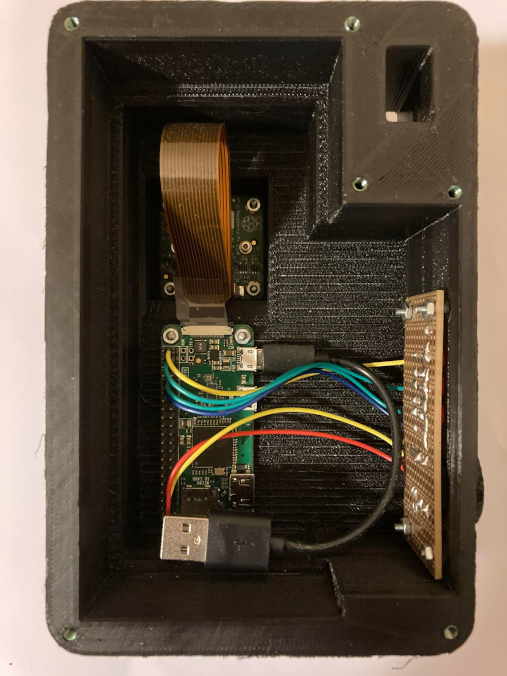
There are 4 main components of the design: the microprocessor (Raspberry Pi Zero Wireless), image sensor (Raspbery Pi HQ Camera), control board (cusom made) and a power source (5V/2A powerbank).
All processing is done on the microprocessor which operates as the main unit. The main unit communicates with the control board to indicate operational status (power on/off, exposing photo/recording video, out of film) and recieve the trigger signal.
The software running on the main unit ensures only 36 photos can be taken before running out of film.

III. Control board
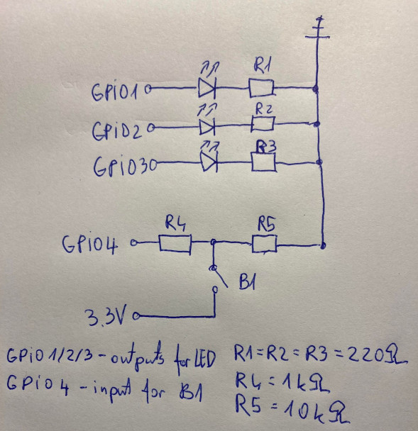
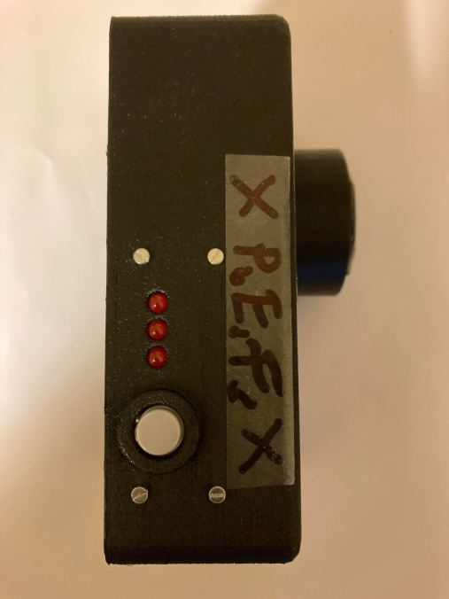
I designed a control board for trigger button and indicator LEDs. 3 LEDs were planned: "power on", "exposing" and "out of film". The control board is connected directly to GPIOs/3.3V/GND of the RPi. Below is a quick schematics for the control board, some of the resistance values might not be super accurate. I use 3 220[Ohm] resistors to limit LED currents (R1,R2,R3) and a 1[kOhm] protective resistor (R4) in series for the input GPIO and a 10[kOhm] pull-down resistance (R5) for the input GPIO.
IV. Optics
At first I decided to start with a lenseless pinhole camera for simplicity of the design and to reduce the cost (lenses are expensive). Over time I actually started enjoying the esthetic of pinhole camera photos and experimenting with different multipinhole setups. To create a pinhole optics I cut out a piece of metal and puctured the smallest hole I could in the center of it. Then I taped it on top of the lens mount of RPiHQ camera. I used a thick electrical tape to endure no light leaks (this is very important).
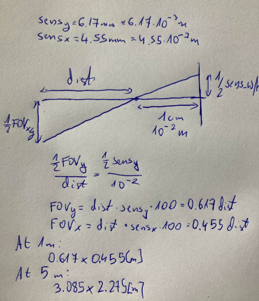
One of the problems I encountered is that the size of the sensor is quite small (6.17[mm]x4.55[mm]). Due to dimensions of the lens mount element, the pinhole was placed +-1[cm] away from the sensor and this results in quite narrow field of view (see calucations below). Due to narrow field of view it's fairly hard to aim the camera.
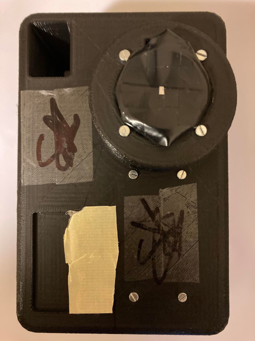
V. Mechanical design
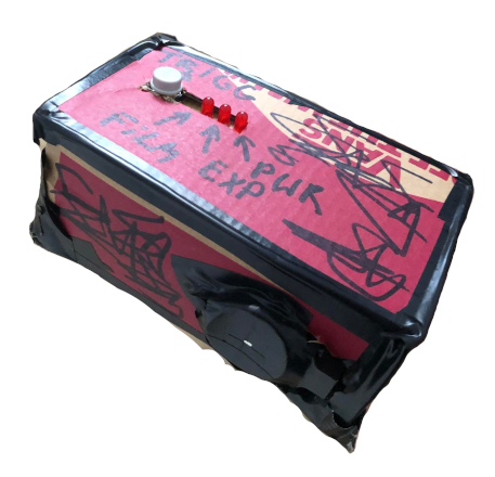
The first prototype was just pushed into a shoe box. It worked well but the durability was lacking so I decided to 3d print a proper stable box.
VI. Source code
Github: digital pinhole
VII. Samples